Mon - Fri: 9:00 - 19:00
 EN

Mon - Fri: 9:00 - 19:00
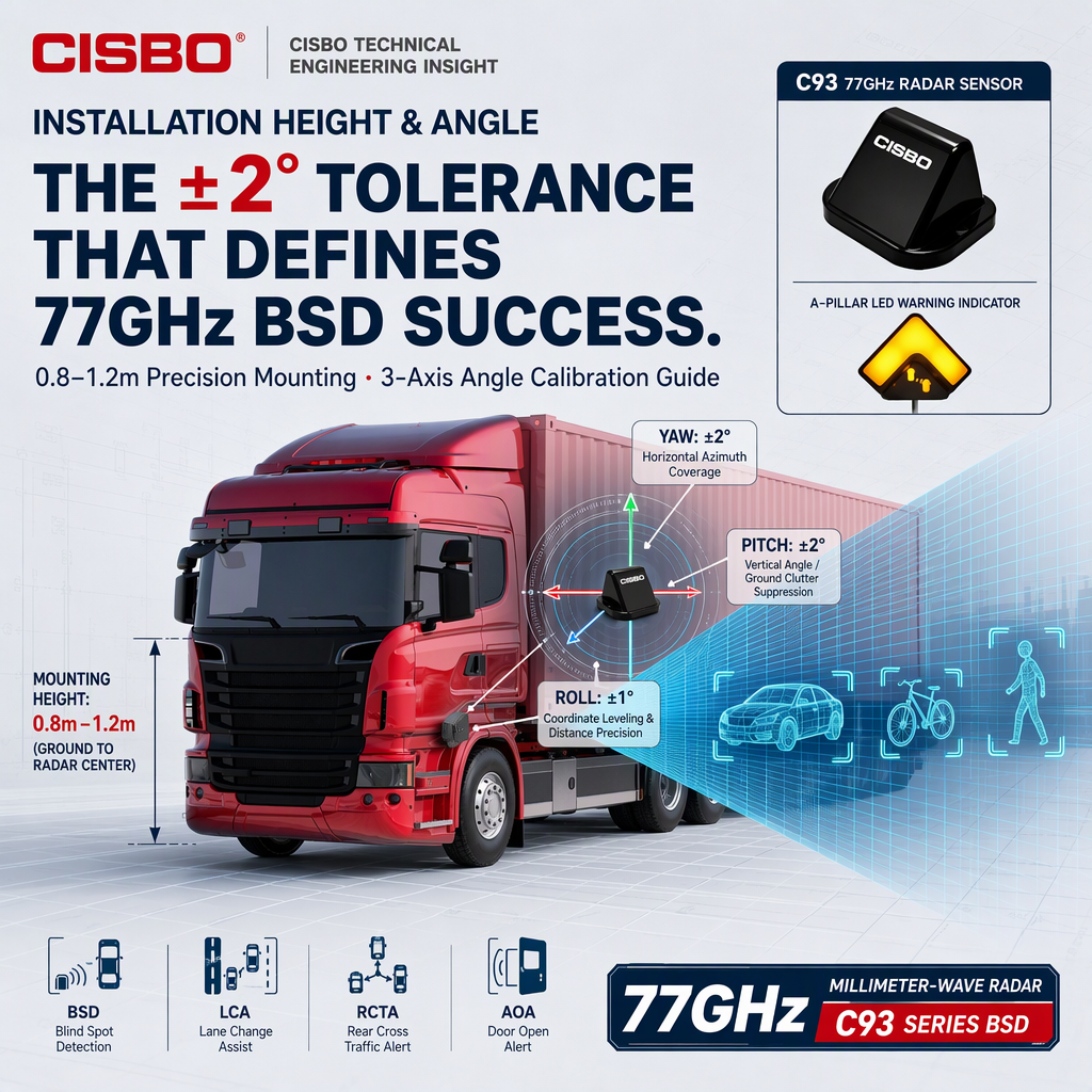
The same 77GHz millimetre-wave blind spot detection system runs clean on Fleet A and throws constant false alarms on Fleet B — or stays silent at the moment it matters most.
In twenty-three years we have walked onto a great many installation sites. When these complaints are traced to the end, it is rarely the product that failed. It is almost always something that was “made to do” during installation. Two things get compromised most often: where the radar is mounted, and at what angle.
This article is not about products. It is about installation. Mount it wrong and no radar, however good, will save you.
Before the argument over height, there is a more fundamental question: where on this vehicle should the radar go?
Different vehicle types offer entirely different mounting positions, and the position decides whether you have any choice over height and angle at all.
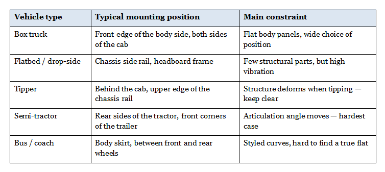 Once the position is fixed, height can be discussed. Adjusting angle before fixing position is like drawing lines on a sheet of paper that is not laid flat yet.
A radar has three mounting angles in three-dimensional space: yaw, pitch and roll. A deviation in any one of them directly distorts what the algorithm perceives.
Get yaw wrong and the radar either reads reflections off the vehicle's own body as obstacles, or misses the very zone it was installed to cover.
This is the main source of false alarms.
Pitch has the narrowest tolerance window of the three, because it has to manage two things that pull against each other: don't sweep the road, and don't miss low targets.
Roll deviation tilts the entire detection coordinate frame, producing geometric error in every distance the system reports. It is the angle most often overlooked, because during installation it is almost invisible to the eye.
Of the three, yaw and pitch bear most directly on whether warnings are correct; roll affects distance accuracy. Based on our installation experience:
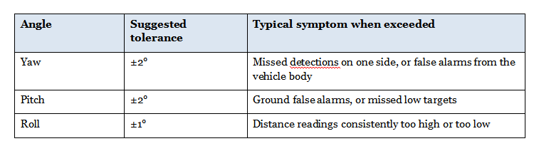
These three numbers are the “two degrees” in the title. They are not some mysterious rule of thumb; they are the permissible deviation boundary for each angle. Beyond that boundary, no amount of software adjustment will put it right.
Many installers instinctively mount the radar as high as possible, on the assumption that a wider view must be better. In practice, mounting height has to match vehicle width and the required detection width.
Mount too high and the dead zone directly beneath the radar grows, so small targets at close range are lost. Mount too low and ground clutter strengthens, and the system starts raising nuisance alarms.
The right height is the one that covers the full length of the vehicle side while leaving enough vertical spread to cover the zone from ground level up to an adult's shoulder.
Under our own test conditions, the sensor mounting height for truck-type vehicles is 0.8–1.2 m. That figure is not a guess. Our detection-range calibration is carried out within this height range — mount the sensor higher and the downward angle steepens, so low targets at close range are the first to disappear; mount it lower and ground reflections arrive first.
This is also why we insist on publishing test conditions alongside the product specification: a detection range quoted without conditions is a promise nobody can verify.
On real installations, curved body panels, structural obstructions and modified chassis all make the “ideal” angle physically unachievable.
The common mistake is to force the install and then raise the algorithm's sensitivity to compensate.
That road is dangerous. Raise sensitivity and false alarms rise with it; false alarms rise and the driver stops trusting the system; the driver stops trusting it and switches it off. A system that has been switched off has a protective capability of zero.
Our advice runs the other way: if the angle cannot be optimal, give up some detection range on that side, lower the threshold in software, and accept a system with a shorter reach but a reach you can stand behind.
Better a system with slightly less range that is accurate, than a system with greater range that is full of false alarms.
Because the real value of a safety device is not on the specification sheet — it is in whether the driver is willing to leave it switched on.
On a site with no laser alignment tool and no anechoic chamber, work in this order.
Confirm the install with external tools. Never use the system's own readings to validate itself.
If this step does not pass, do not go any further. With a physically skewed install, the readings you see after power-up already carry the error. Both sides are wrong together, which makes it easy for them to appear to “agree”.
Only after the physical check passes, power up and test point by point with a corner reflector at 1.5 m, 3 m and 5 m, checking whether the distances the system reports fall within a sensible band.
If the readings are consistently high or low, look at roll first, then pitch, and only then touch algorithm parameters.
This is the step most often skipped, and the one most likely to come back.
Bracket stability matters as much as angle. Vibration over time will walk the sensor away from where it was set — today's ±2° can become ±5° six months later. How long any calibration can be trusted depends on whether the bracket survives the road.
So after installation, apply anti-loosening treatment between the bracket and the vehicle body, and write “periodic angle re-check” into the vehicle's maintenance schedule.
A blind spot detection system is not a part you bolt on and forget. It is a system.
Buying a competent millimetre-wave BSD is only the first step. Making it warn accurately at every position on this vehicle, over every stretch of road, through every articulation angle — that is the real challenge.
Those two degrees are not folklore. They are tolerance. Hold the tolerance and the numbers on the specification sheet mean something; miss it and no figure printed there counts for anything.
CISBO — 23 years manufacturing commercial vehicle safety systems | IATF 16949 certified | Shenzhen, China | www.szcisbo.com
Shenzhen CISBO Technology Co., Ltd. specializes in automotive electronic products including BSD, PWAS, AI monitoring, parking sensors, and rear view systems. With 23 years of experience and global certifications, we deliver high-quality solutions for safer driving. Explore our products and services today.
6F, Building 3, Lijincheng Industry Park, Gongye East Road, Longhua, Longhua New District, Shenzhen, 518109, China
Copyright © 2026 Shenzhen CISBO Technology Co., LTD. All rights reserved. Privacy Policy 粤ICP备:05005734号